Making Your Own Crimpdeq
This chapter explains how to build your own Crimpdeq prototype.
1. Required Materials
- ESP32-C3-DevKit-RUST-1
- Other ESP32 boards can be used, but you will need a way to charge the battery.
- Battery Holder
- 18650 Battery
- Other batteries might also work, as long as they can power the device.
- Crane Scale or Amazon alternative
- Other crane scales might also work.
- HX711 module:
- [Optional] Resistors:
- 1× 33 kΩ resistor
- 1× 10 kΩ resistor
2. Disassemble the Crane Scale
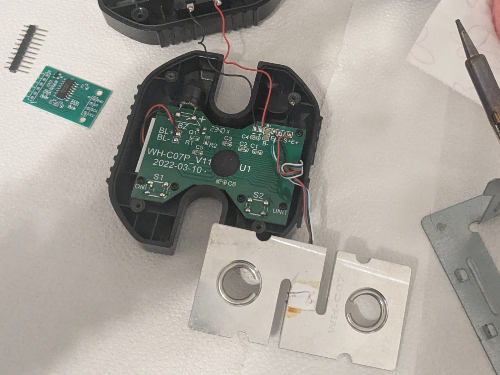
- Desolder the battery connections.
- Desolder the four wires of the load cell (
E-,S-,S+andE+) from the PCB.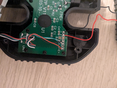
- Unscrew and remove the PCB along with the display.
3. Soldering
-
Modify the HX711 module:
- Set the sample rate to 80 Hz: Most HX711 modules ship with the
RATEpin tied toGND, which sets a 10 Hz sample rate. To switch to 80 Hz:
- Cut the PCB trace to the
RATEpin.- This can be done by carefully scratching the trace with a knife.
- Verify with a multimeter that
GNDandRATEare no longer connected.- Take care not to damage adjacent traces.
- Solder the
RATEpin to theDVDDpin. - Verify with a multimeter.
- Cut the PCB trace to the
- [Optional] Optimize measurements for 3.3 V: Most HX711 modules are configured for 5 V operation. To improve measurements at 3.3 V:
- Solder, in parallel, a resistor between 20 kΩ and 27 kΩ across
R1.R1is the highlighted resistor in the image: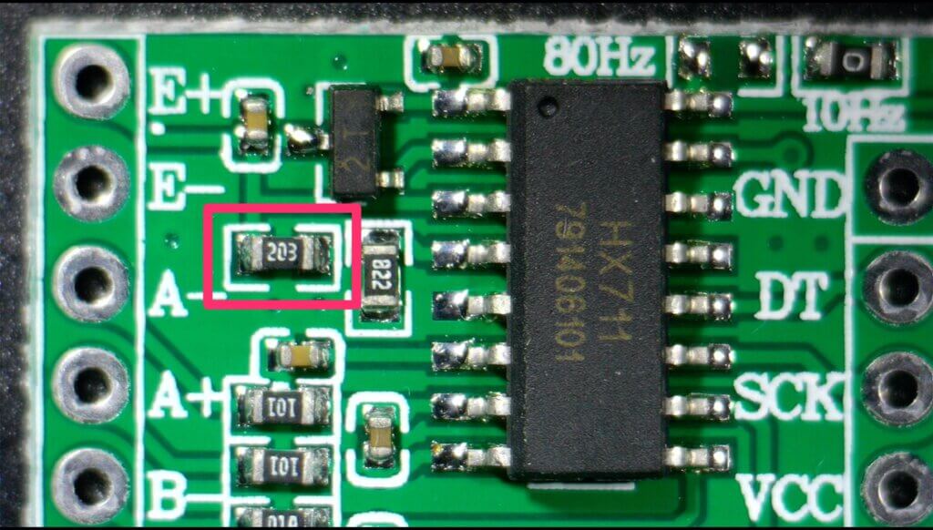
- For more information, see this blog post.
- This step is optional, but it improves measurement quality.
- Solder, in parallel, a resistor between 20 kΩ and 27 kΩ across
- Set the sample rate to 80 Hz: Most HX711 modules ship with the
-
Connect the Load Cell to the HX711:
- Solder the 4 wires from the crane scale to the HX711. Typical color mapping:
HX711 Pin Load Cell Pin Description E+ E+ (Red) Excitation positive (to load cell) E- E- (Black) Excitation negative (to load cell) S+ S+ (Green) Signal positive (from load cell) S- S- (White) Signal negative (from load cell) ⚠️ Note: on some HX711 modules the
S+/S-pins are labeledA+/A-. -
Connect the HX711 to the ESP32-C3-DevKit-RUST-1:
| HX711 Pin | ESP32-C3 Pin | Description |
|---|---|---|
| VCC | 3.3V | Power supply (3.3V) |
| GND | GND | Ground |
| DT (Data) | GPIO4 | Data output from HX711 |
| SCK (Clock) | GPIO5 | Clock signal for communication |
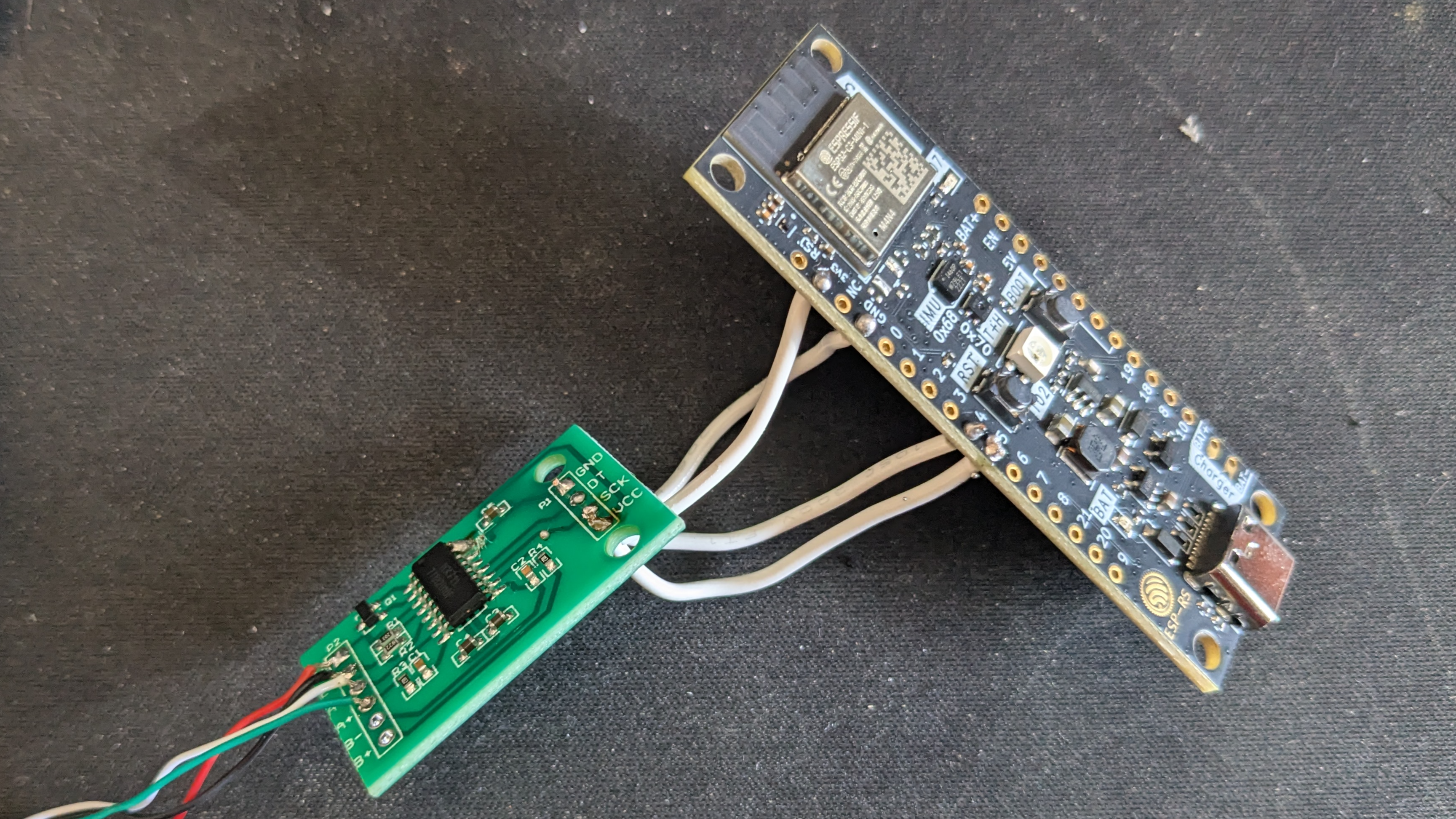
- [Optional] Solder the voltage divider:
- Solder one end of the 33kΩ resistor to the
B+pin on the ESP32-C3-DevKit-RUST-1. - Join the other end of the 33kΩ resistor and one end of the 10kΩ resistor together, and connect that junction to
GPIO1on the ESP32-C3-DevKit-RUST-1. - Solder the remaining end of the 10kΩ resistor to
GND.
- The firmware expects the battery sense on
GPIO1by default. Adjust the firmware configuration if you wire a different pin.
- Solder one end of the 33kΩ resistor to the
- Verify all connections with a multimeter.
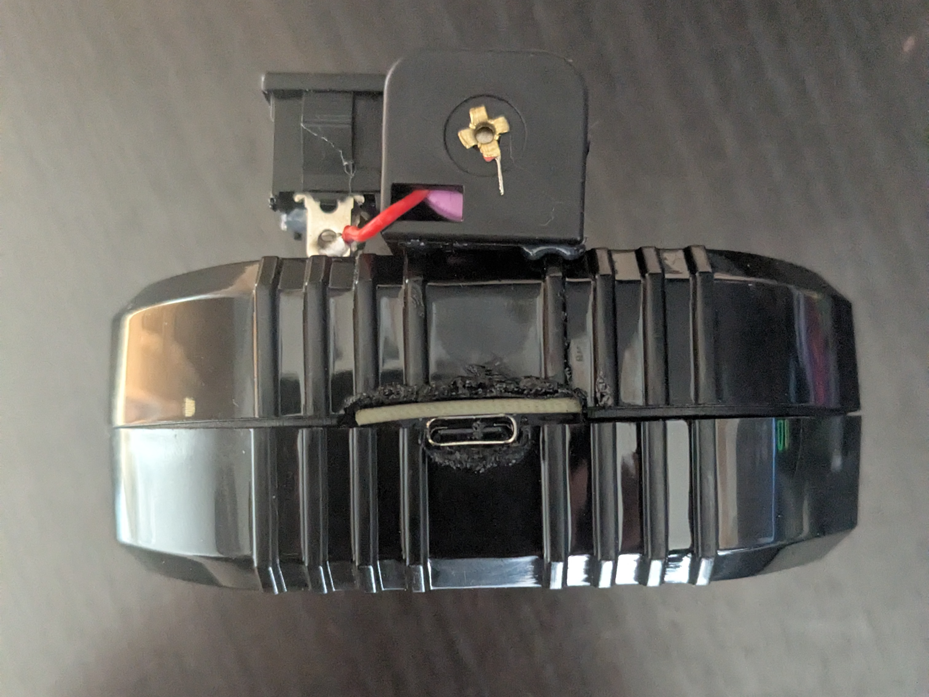
4. Adapt the Scale Case
- Create space for the USB connector.
- For example: place the board to mark the opening with a pen, then carefully heat a knife and melt the plastic to create space.
- Install the battery holder:
- Glue the battery holder with silicone. Leave the lid for the scale’s original batteries open, you will route the two battery holder wires through that opening.
- Solder the positive wire (red) of the battery holder to a switch or button to turn the device on/off, then solder the other pin of the switch/button to the
B+pin of ESP32-C3-DevKit-RUST-1. - Solder the negative wire (black) of the battery holder to the
B-pin of the ESP32-C3-DevKit-RUST-1.
- Close the case:
- Ensure all components are securely installed before closing the case.
- Ensure all components are securely installed before closing the case.
5. Upload the firmware
-
Connect your device with a USB‑C cable.
-
Pull the
crimpdeq-firmwarerepository:git clone https://github.com/crimpdeq/crimpdeq-firmwareIf you don’t have git installed, you can click the green “Code” button on the repository and use the “Download ZIP” option.
-
Upload the firmware to your device:
- Download the binary from the desired GitHub releases.
- Flash your device
- Using esp.huhn.me.
- Click “Connect” and select the serial port of your ESP board.
- Upload your
.binfile. - Click “Program”.
- See this blog post for more details.
- Using Adafruit ESPTool
- Click Connect and select the serial port of your ESP board (should be named
USB/JTAG serial debug unit...) - Upload your
.binfile at offset0x10000 - Click Program
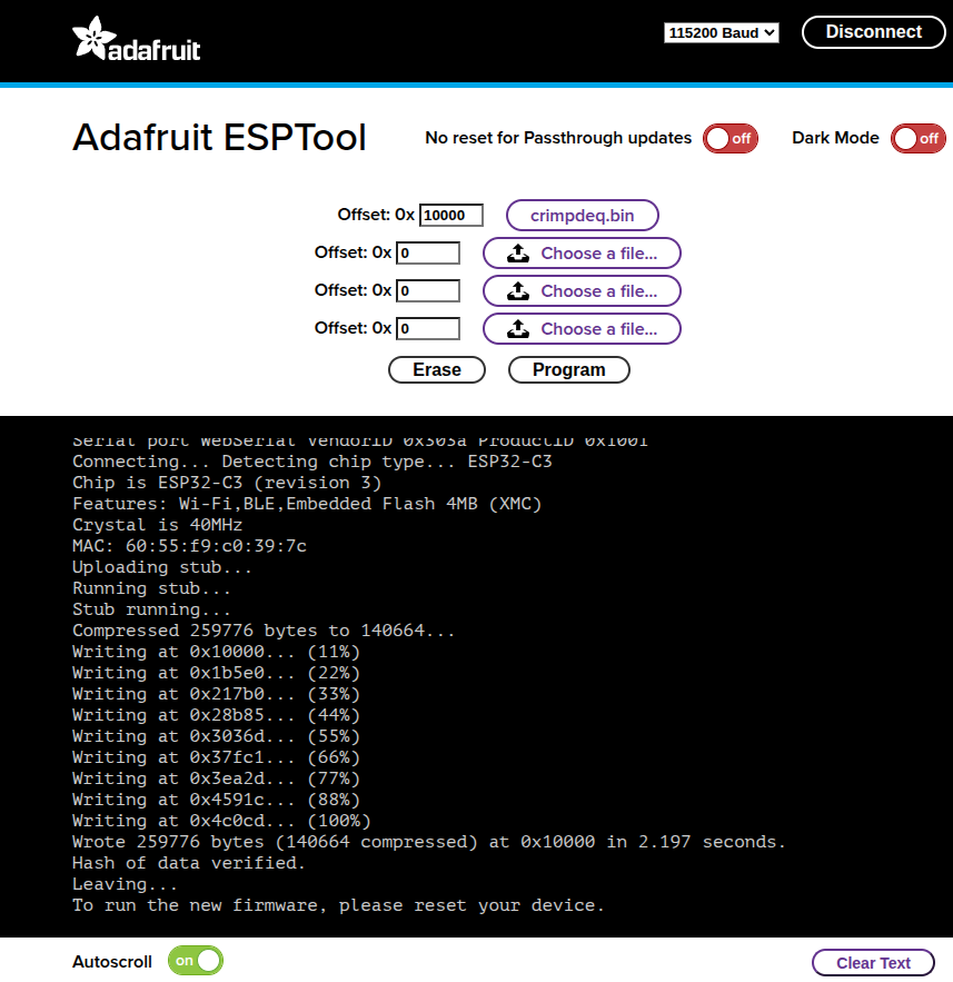
- Click Connect and select the serial port of your ESP board (should be named
⚠️ Note: If this uploading method doesn’t work for you, refer to the Firmware chapter. You may need to install the prerequisites, build, and flash the firmware.
-
Check whether the default calibration values work for your scale:
- Connect your device with the Frez or Tindeq apps.
- Use the “Live View” option.
- Measure a known weight and verify that Crimpdeq measures the right value.
- If Crimpdeq calibration is off, see the Calibration chapter.